 Ukraine (UA)
 Germany (DE)
 Italy (IT)
 India (EN)
 Turkey (TR)
 France (FR)
 Spain (ES)
 Japan (JP)
 South Korea (KR)
Thyristor Modules MT3, MT4, MT5

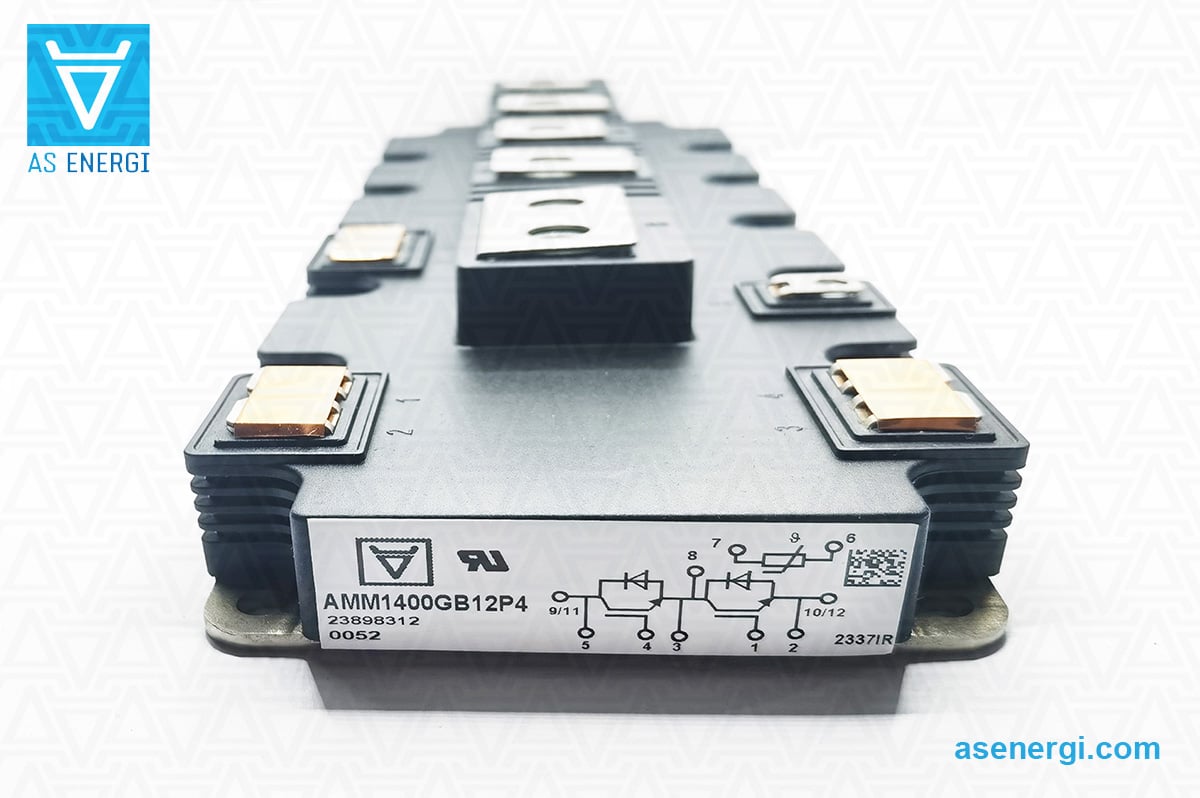
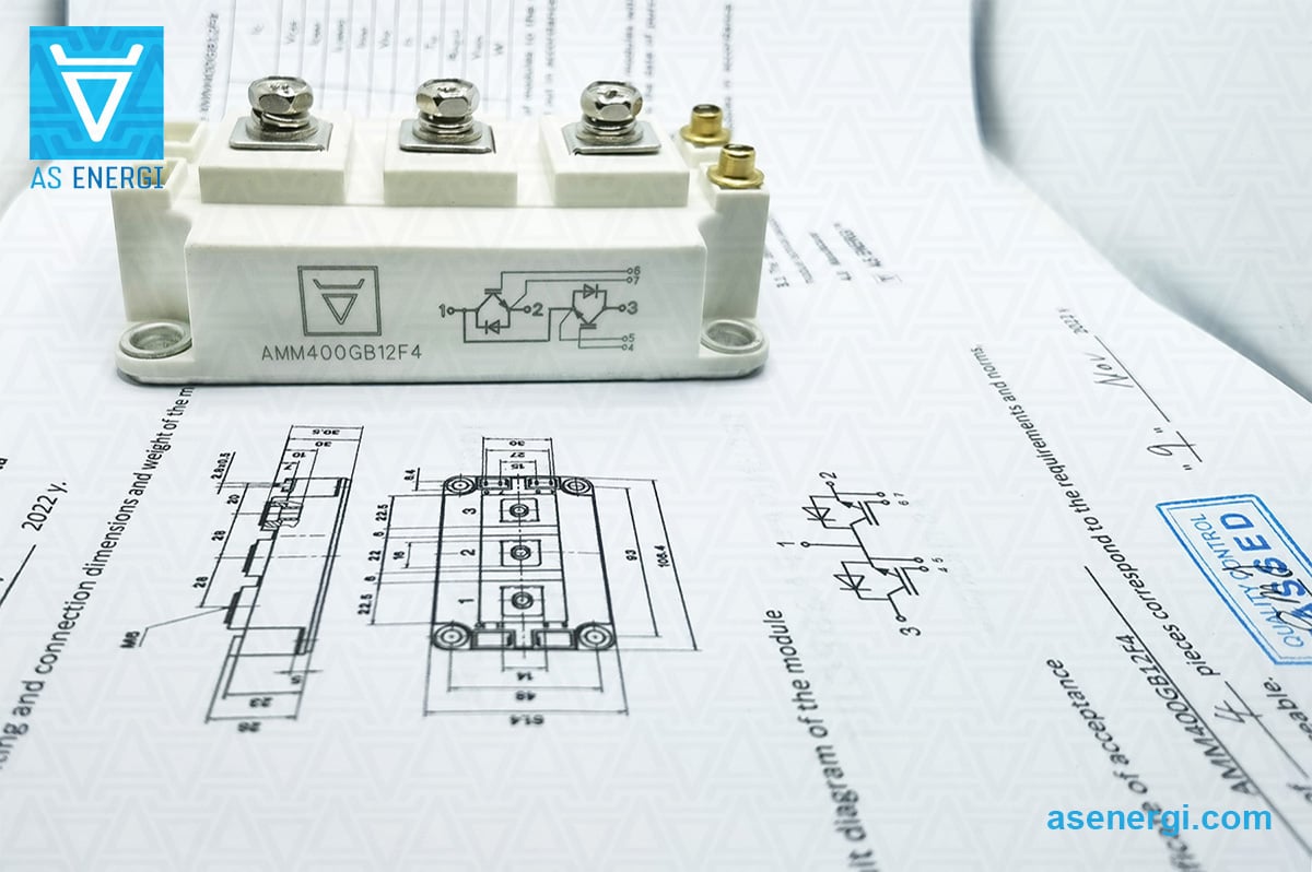
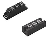
Dual thyristor modules MT AS ENERGITM are a monolithic design with two semiconductor thyristors (type thyristor-thyristor), operate in DC and AC circuits with loads from 115A up to 1250A and reverse pulse voltages up to 6500V.
Wiring diagram of modules: MT3 – half-bridge; MT4 – common cathode circuit; MT5 – common anode circuit.
High energy-thermocyclic resistance and reliable operation of MT low-frequency thyristor modules at switching high currents is achieved due to their design features and stable galvanic isolation parameters:

- dielectric strength of insulation between potential-free base and leads reaches 3600V under normal climatic conditions and 1500V at high humidity;
- housing is made of non-combustible thermopolymer;
- dielectric strength of insulation between main and control leads reaches 2500V under normal climatic conditions and 1500V at high humidity;
- insulation resistance between potential-free base and outputs under normal climatic conditions is at least 50Mohm and no less than 5Mohm at high humidity;
- insulation resistance between main and control leads under normal climatic conditions is at least 1000Mohm and no less than 100Mohm at high humidity.
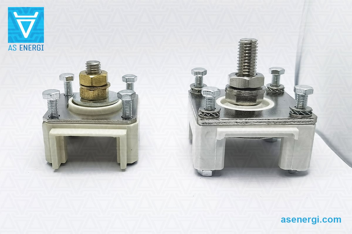
Thyristor modules MT3, MT4, MT5 have a clamping design, mounting with screws through the through mounting holes in the housing. The wires are fastened with nickel-plated terminals, under which the test points for measuring the pulse direct voltage are placed. Main leads are located on the top of the housing and are numbered 1, 2, 3. Control leads are marked in the wiring diagram as G1, G2. Additional cathodes are marked in the wiring diagram as K1, K2.
When mounting thyristor modules, special attention should be paid to the tightness of the mating surfaces – concavity more than 0.03 mm is not allowed.
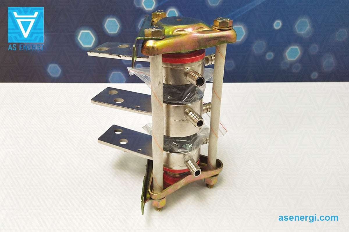
To mount additional cooling (radiators or coolers are used), mounting holes are provided in the housing of the thyristor potential-free modules. A special thermally conductive substrate lubricated with thermal paste must be used between the module and the cooling element.
Thyristor modules MT3, MT4, MT5 are used in various power installations - power and control units, power regulators, AC regulators, inverters, motor starters and controls, temperature controllers of blast furnaces or chemical processes, welding equipment, etc.
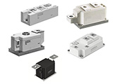
Our modules are offered in several dual and single device topologies for almost all phase control or rectifier applications.
Our company provides a quality guarantee for thyristor / diode modules of 2 years from the date of purchase. When supplying thyristor / diode modules, if necessary, we provide technical passport and certificate of conformity.
The final price for thyristor / diode modules depends on the class, quantity, delivery terms, manufacturer, country of origin and form of payment.
For questions regarding the acquisition of Power Modules, Thyristors, Diodes, send an email request to:
And we will provide you a commercial offer for delivery.
For a large number, we will provide an individual price!!!
We are open to manufacture products at our production facilities
according to your requests and technical task.
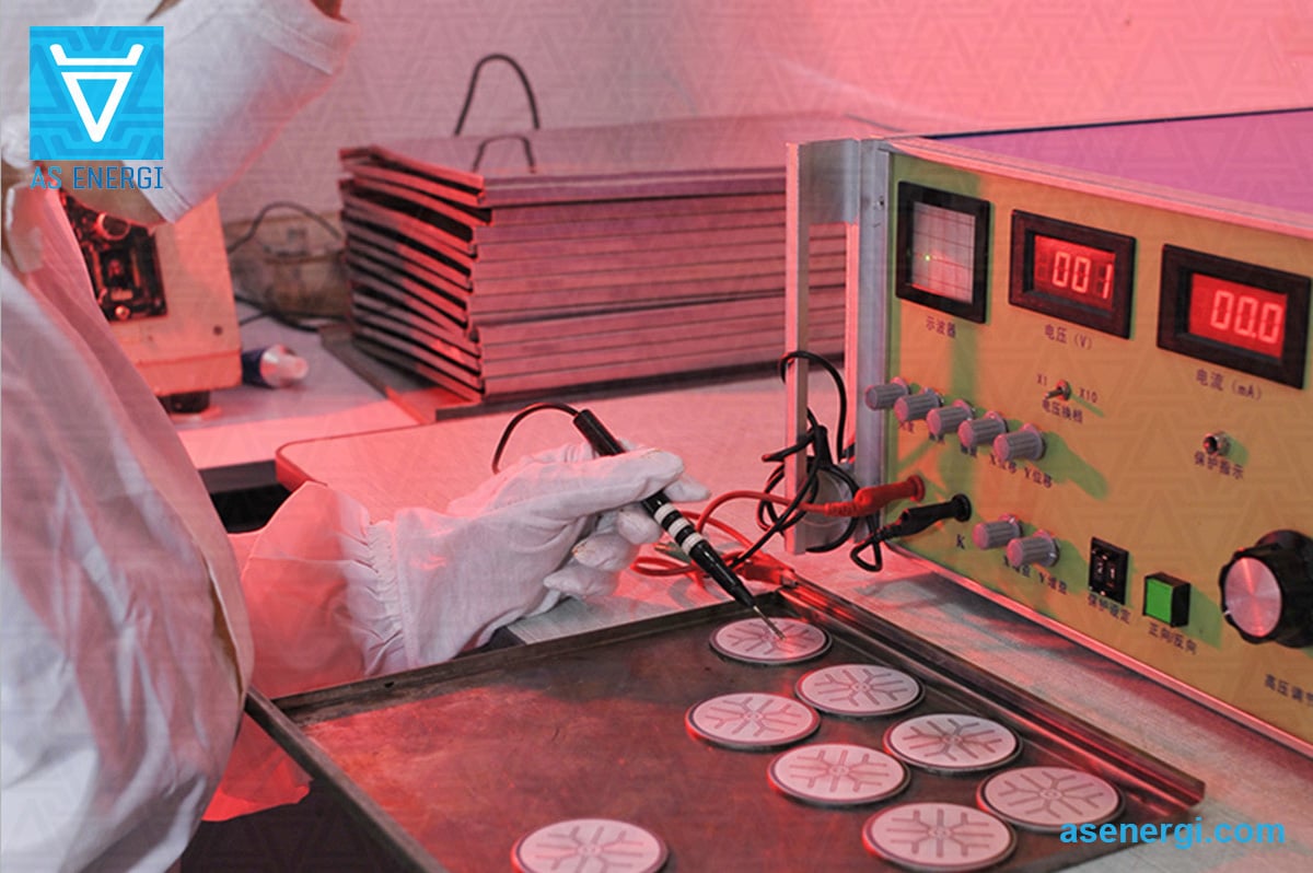
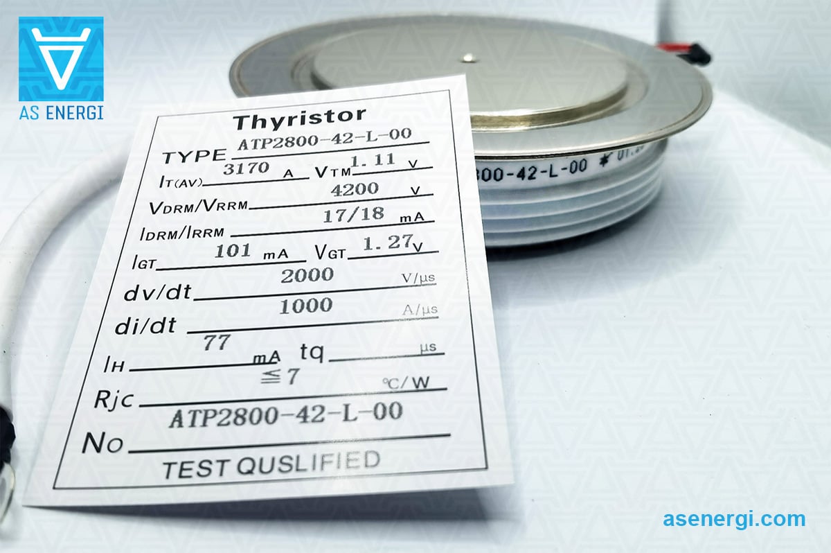
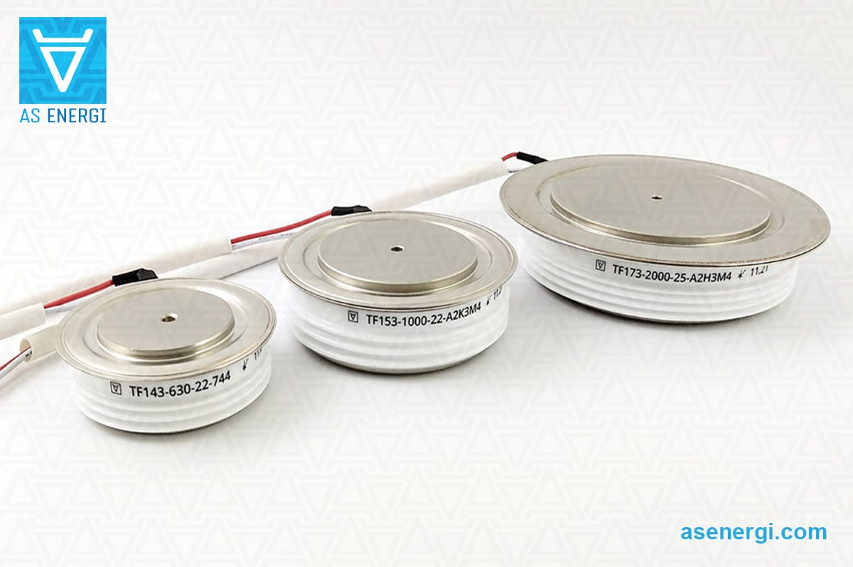
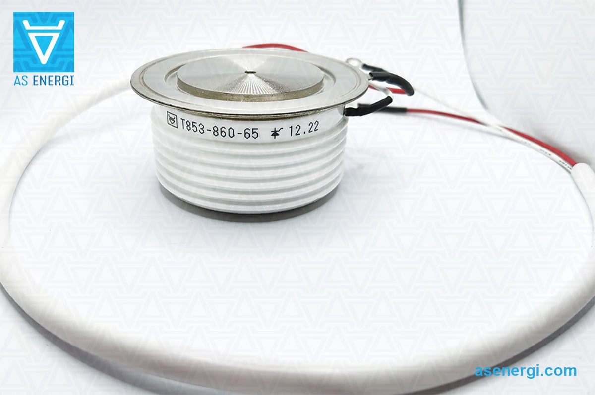
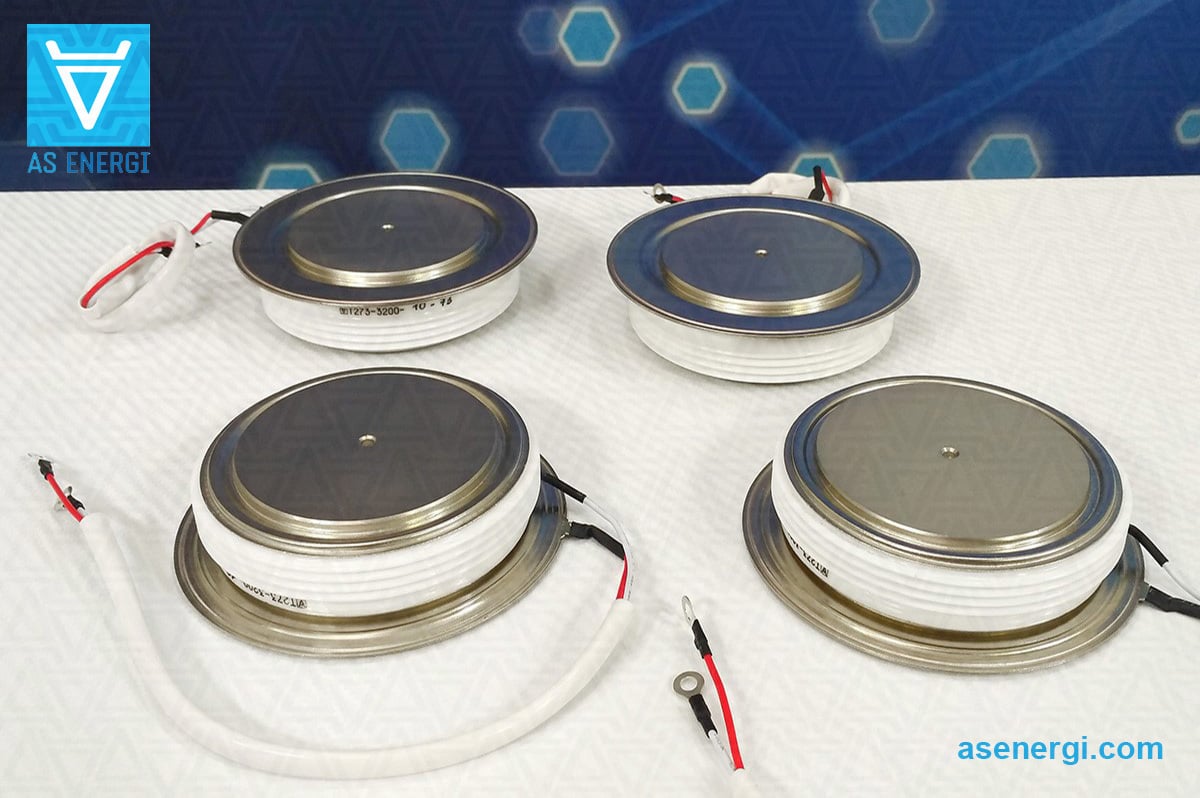
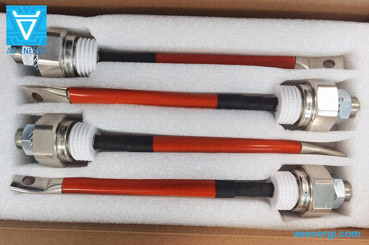
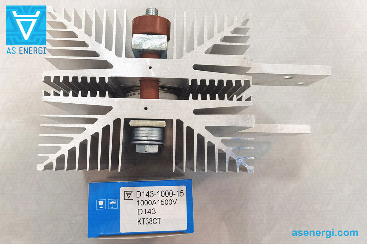
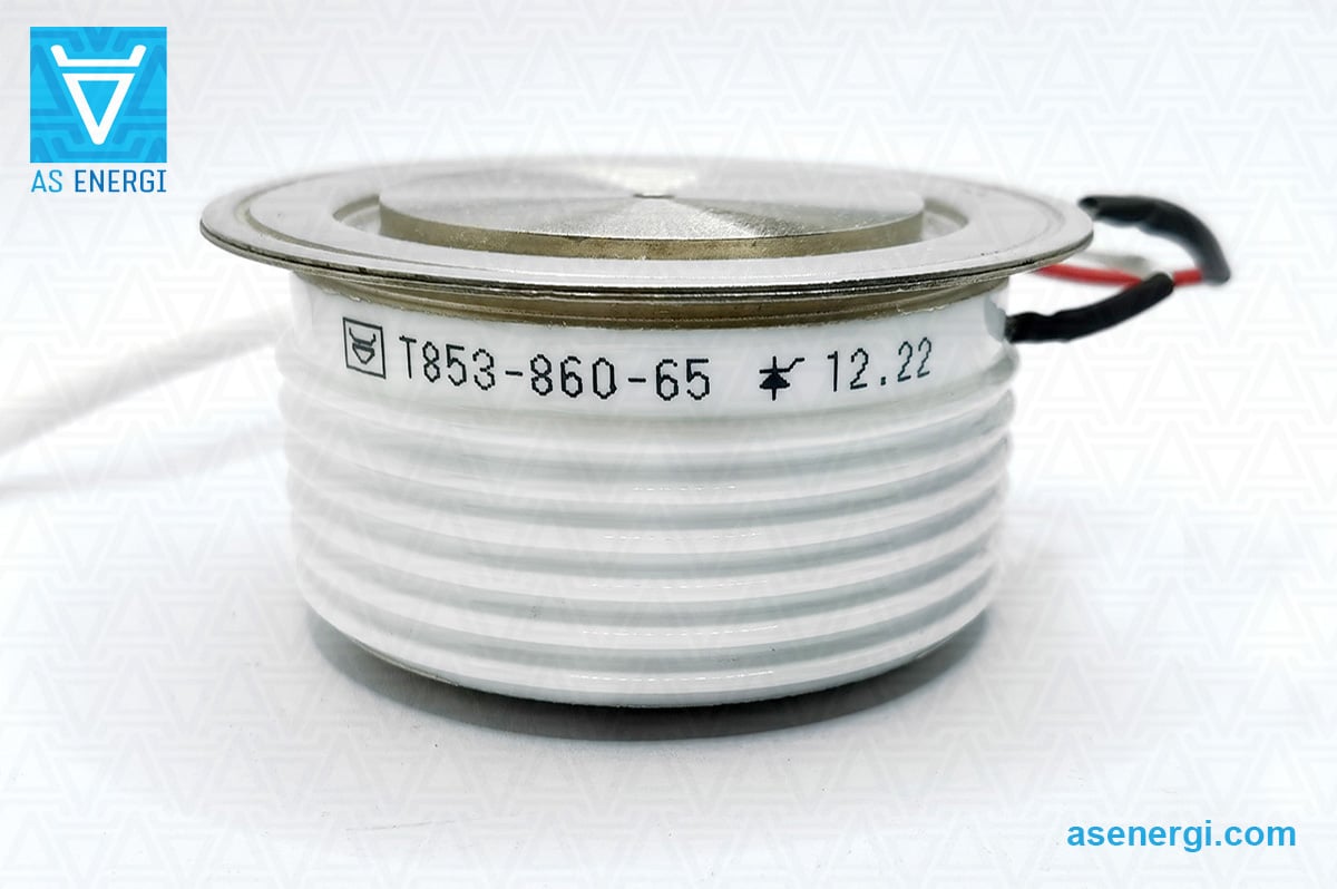
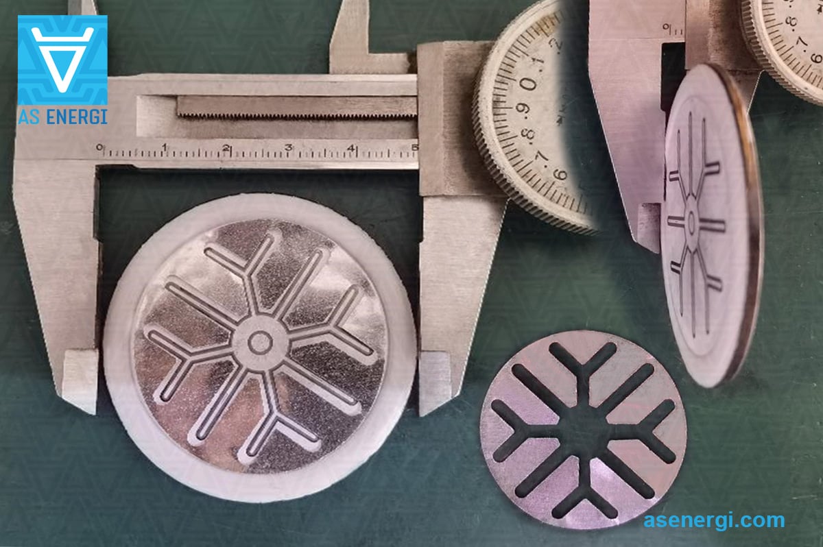
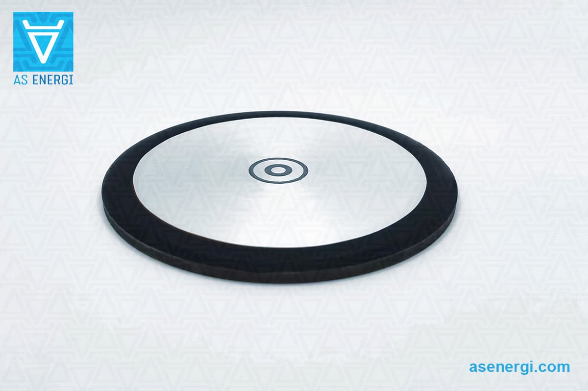
Photo Gallery
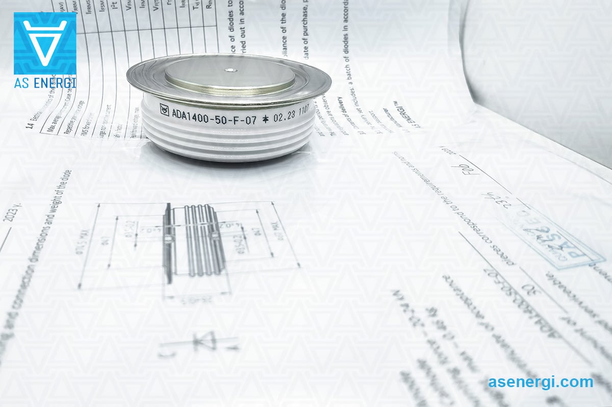
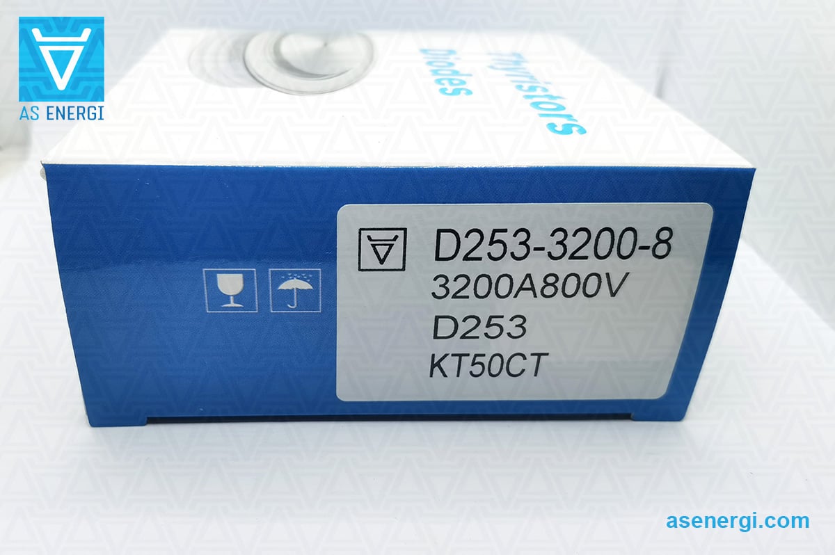
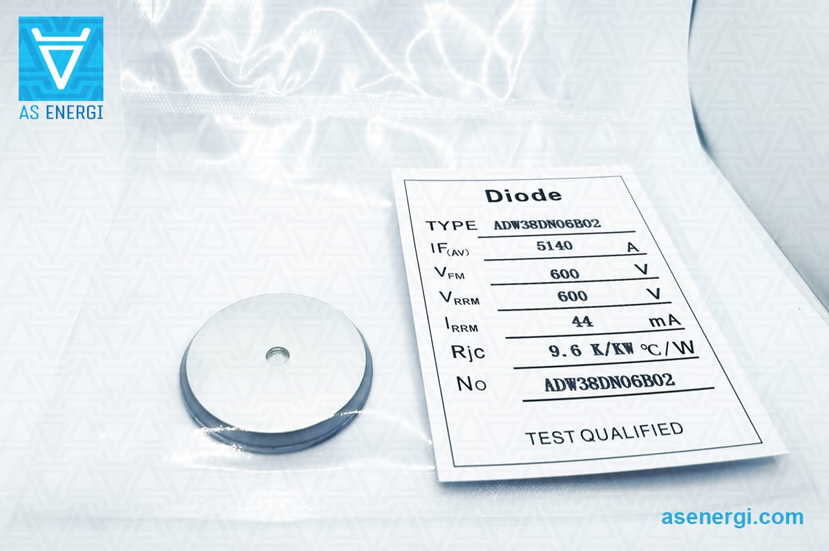
The photo gallery shows many different semiconductor devices, semiconductor chips and SCRs produced by AS ENERGITM, examples of test reports.

General specifications of Thyristor-Thyristor Modules MT3, MT4, MT5
| Photo | Series | Average forward current, IT(AV) |
Voltage, VRRM |
Connection diagram | Package | Dimensions | |
 |
MT3-115 | 115A | 3000 - 3600V |  |
F | 94x34x30 | |
|
MT4-115 | 115A | 3000 - 3600V |  |
F | 94x34x30 | |
|
MT3-125 | 125A | 2400 - 2800V | |
F | 94x34x30 | |
|
MT4-125 | 125A | 2400 - 2800V | |
F | 94x34x30 | |
|
MT3-130 | 130A | 2400 - 2800V | |
F | 94x34x30 | |
|
MT4-130 | 130A | 2400 - 2800V | |
F | 94x34x30 | |
|
MT3-160 | 160A | 2000 - 2200V | |
F | 94x34x30 | |
|
MT3-160 | 160A | 3000 - 3600V | |
C1 | 92x52x50 | |
|
MT4-160 | 160A | 2000 - 2200V | |
F | 94x34x30 | |
|
MT4-160 | 160A | 3000 - 3600V | |
C1 | 92x52x50 | |
|
MT5-160 | 160A | 3000 - 3600V |  |
C1 | 92x52x50 | |
|
MT3-165 | 165A | 2000 - 2200V | |
F | 94x34x30 | |
|
MT4-165 | 165A | 2000 - 2200V | |
F | 94x34x30 | |
|
MT3-200 | 200A | 1000 - 1800V | |
F | 94x34x30 | |
|
MT3-200 | 200A | 2600 - 2800V | |
C1 | 92x52x50 | |
|
MT4-200 | 200A | 1000 - 1800V | |
F | 94x34x30 | |
|
MT4-200 | 200A | 2600 - 2800V | |
C1 | 92x52x50 | |
|
MT5-200 | 200A | 2600 - 2800V | |
C1 | 92x52x50 | |
|
MT3-201 | 201A | 1000 - 1800V | |
F | 94x34x30 | |
|
MT4-201 | 201A | 1000 - 1800V | |
F | 94x34x30 | |
|
MT5-201 | 201A | 1000 - 1800V | |
F | 94x34x30 | |
 |
MT3-240 | 240A | 4600 - 6500V |
|
A2 | 124x60x52 | |
|
MT4-240 | 240A | 4600 - 6500V | |
A2 | 124x60x52 | |
|
MT5-240 | 240A | 4600 - 6500V | |
A2 | 124x60x52 | |
|
MT3-250 | 250A | 2000 - 2400V | |
C1 | 92x52x50 | |
|
MT3-250 | 250A | 3800 - 4400V | |
A2 | 124x60x52 | |
|
MT4-250 | 250A | 2000 - 2400V | |
C1 | 92x52x50 | |
|
MT4-250 | 250A | 3800 - 4400V | |
A2 | 124x60x52 | |
|
MT5-250 | 250A | 2000 - 2400V | |
C1 | 92x52x50 | |
|
MT5-250 | 250A | 3800 - 4400V | |
A2 | 124x60x52 | |
|
MT3-260 | 260A | 3800 - 4400V | |
A2 | 124x60x52 | |
|
MT4-260 | 260A | 3800 - 4400V | |
A2 | 124x60x52 | |
|
MT5-260 | 260A | 3800 - 4400V | |
A2 | 124x60x52 | |
|
MT3-320 | 320A | 1000 - 1800V | |
C1 | 92x52x50 | |
|
MT3-320 | 320A | 3000 - 3600V | |
A2 | 124x60x52 | |
|
MT4-320 | 320A | 1000 - 1800V | |
C1 | 92x52x50 | |
|
MT4-320 | 320A | 3000 - 3600V | |
A2 | 124x60x52 | |
|
MT5-320 | 320A | 1000 - 1800V | |
C1 | 92x52x50 | |
|
MT5-320 | 320A | 3000 - 3600V | |
A2 | 124x60x52 | |
|
MT3-400 | 400A | 2000 - 2800V | |
A2 | 124x60x52 | |
 |
MT3-400 | 400A | 3800 - 4400V |  |
D | 150x77x84 | |
|
MT4-400 | 400A | 2000 - 2800V | |
A2 | 124x60x52 | |
|
MT4-400 | 400A | 3800 - 4400V |  |
D | 150x77x84 | |
|
MT5-400 | 400A | 2000 - 2800V | |
A2 | 124x60x52 | |
|
MT5-400 | 400A | 3800 - 4400V |  |
D | 150x77x84 | |
|
MT3-430 | 430A | 2000 - 2400V | |
A2 | 124x60x52 | |
|
MT4-430 | 430A | 2000 - 2400V | |
A2 | 124x60x52 | |
|
MT5-430 | 430A | 2000 - 2400V | |
A2 | 124x60x52 | |
|
MT3-500 | 500A | 1400 - 1800V | |
A2 | 124x60x52 | |
|
MT3-500 | 500A | 3000 - 3600V | |
D | 150x77x84 | |
|
MT4-500 | 500A | 1400 - 1800V | |
A2 | 124x60x52 | |
|
MT4-500 | 500A | 3000 - 3600V | |
D | 150x77x84 | |
|
MT5-500 | 500A | 1400 - 1800V | |
A2 | 124x60x52 | |
|
MT5-500 | 500A | 3000 - 3600V | |
D | 150x77x84 | |
|
MT3-540 | 540A | 1400 - 1800V | |
A2 | 124x60x52 | |
|
MT4-540 | 540A | 1400 - 1800V | |
A2 | 124x60x52 | |
|
MT5-540 | 540A | 1400 - 1800V | |
A2 | 124x60x52 | |
|
MT3-595 | 595A | 1400 - 1800V | |
A2 | 124x60x52 | |
|
MT4-595 | 595A | 1400 - 1800V | |
A2 | 124x60x52 | |
|
MT5-595 | 595A | 1400 - 1800V | |
A2 | 124x60x52 | |
|
MT3-630 | 630A | 1000 - 1200V | |
A2 | 124x60x52 | |
|
MT3-630 | 630A | 2600 - 2800V | |
D | 150x77x84 | |
|
MT4-630 | 630A | 1000 - 1200V | |
A2 | 124x60x52 | |
|
MT4-630 | 630A | 2600 - 2800V | |
D | 150x77x84 | |
|
MT5-630 | 630A | 1000 - 1200V | |
A2 | 124x60x52 | |
|
MT5-630 | 630A | 2600 - 2800V | |
D | 150x77x84 | |
|
MT3-650 | 650A | 1000 - 1200V | |
A2 | 124x60x52 | |
|
MT4-650 | 650A | 1000 - 1200V | |
A2 | 124x60x52 | |
|
MT5-650 | 650A | 1000 - 1200V | |
A2 | 124x60x52 | |
|
MT3-700 | 700A | 1400 - 1800V | |
A2 | 124x60x52 | |
|
MT4-700 | 700A | 1400 - 1800V | |
A2 | 124x60x52 | |
|
MT5-700 | 700A | 1400 - 1800V | |
A2 | 124x60x52 | |
|
MT3-740 | 740A | 2000 - 2400V | |
D | 150x77x84 | |
|
MT4-740 | 740A | 2000 - 2400V | |
D | 150x77x84 | |
|
MT5-740 | 740A | 2000 - 2400V | |
D | 150x77x84 | |
|
MT3-800 | 800A | 1400 - 1800V | |
D | 150x77x84 | |
|
MT4-800 | 800A | 1400 - 1800V | |
D | 150x77x84 | |
|
MT5-800 | 800A | 1400 - 1800V | |
D | 150x77x84 | |
|
MT3-1000 | 1000A | 1000 - 1200V | |
D | 150x77x84 | |
|
MT4-1000 | 1000A | 1000 - 1200V | |
D | 150x77x84 | |
|
MT5-1000 | 1000A | 1000 - 1200V | |
D | 150x77x84 | |
|
MT3-1250 | 1250A | 100 - 800V | |
D | 150x77x84 | |
|
MT4-1250 | 1250A | 100 - 800V | |
D | 150x77x84 | |
|
MT5-1250 | 1250A | 100 - 800V | |
D | 150x77x84 |
Part numbering guide for thyristor–thyristor modules:
| MT | 3 | – | 115 | – | 36 | – | A2 | – | A3 | – | F | – | N |
| MT | – | Thyristor module, |
||||||||||||||||||||||||||||||||||||
| 3 | – | Connection diagram: 3 – half-bridge; 4 – common cathode circuit; 5 – common anode circuit. |
||||||||||||||||||||||||||||||||||||
| 115 | – | Rated current IF(AV), A. | ||||||||||||||||||||||||||||||||||||
| 36 | – | Voltage class VRRM / 100 (Nominal voltage – 3600 V). | ||||||||||||||||||||||||||||||||||||
| A2 | – | Parameter of the critical rate of rise of off-state voltage (dVD/dt)cr:
|
||||||||||||||||||||||||||||||||||||
| A3 | – | Parameter of turn-off time tq:
|
||||||||||||||||||||||||||||||||||||
| F | – | Housing type. | ||||||||||||||||||||||||||||||||||||
| N | – | Ambient conditions: N – Normal. |
Dimensions of thyristor modules MT3, MT4, MT5:
-

Package F
-

Package C1
-

Package А2
-

Package D


Connection diagram of thyristor modules MT3, MT4, MT5:
-

Half-Bridge
-

Common Cathode
-

Common Anode


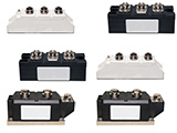
Photo of thyristor modules:


Recommendations for mounting power modules
Heatsink and Surface Specifications, Preparation
In order to ensure good thermal contact and to obtain the thermal contact resistance values specified in the datasheets, the contact surface of the heat sink must be clean and free from dust particles. It is useful to clean the mounting surface of the heat sink with wipes and an alcohol cleaner, e.g. isopropanol, right before the mounting process. The following mechanical specifications have to be met:
– Unevenness of heat sink mounting area must be ≤ 50μm per 100 mm
– Roughness Rz: < 10 μm
– No steps > 10 μm

Heat sink surface specification |
Applying Thermal Paste
Recommended to use stencil printing in order to apply thermal interface material. Recommended to use thermal paste thickness in the range from 50 μm to 100 μm. Applying thermal paste by means of roller is not recommended for mass production as reproducible of an optimized thermal paste thickness cannot be guaranteed.
Mounting torque on heat sink MS
To secure power modules, the use of steel screws in combination with suitable washers and spring lock washers or combination screws is strongly recommended. The specified in datasheet torque value must be observed.
A pre-tightening torque and retightening to the given torque value is recommended. For the screwing process the speed has to be limited and soft torque limitation is recommended to avoid torque peaks, which may occur with pneumatic screwdrivers.

Example of mounting order |
The screws must be tightened in diagonal order with equal torque in several steps until the specified torque value MS has been reached.
 Why choose AS ENERGITM
- Own production facilities, including semiconductor silicon chips production
- European brand - 100% quality, favorable price, short production terms
- Over 20 years of experience in the semiconductor industry
- Clients from more than 50 countries trust us
- 20000 items in the product line for currents from 10A to 15000A, voltages from 100V to 9000V
- We produce analogues of other manufacturers' products
- Guaranteed certified quality, warranty period of operation - 2 years


Quality Warranty
Our products are certified and correspond to international standards.
Our company provides a quality guarantee for products of 2 years.
We provide certificates of conformity, reliability reports, data sheets and technical passports at the request of the customer.

Each product is tested for the main parameters, and Test reports of the parameters for each product are provided.

Geography of partnership
AS ENERGITM company manufactures and supplies power semiconductors to more than 50 countries around the world.

Logistics and Delivery
We deliver our products all over the world with the services of logistics companies: DHL, TNT, UPS, EMS, Fedex, Aramex.
Products can be delivered by any means of transport: air, sea, rail and road.

AS ENERGITM Semiconductors Manufacturing
Our products range includes rectifier diodes, phase control thyristors in disc and stud design, avalanche diodes and thyristors, fast switching, high frequency thyristors, fast recovery, welding and rotor diodes, triacs, bridge rectifiers, power modules (thyristor, diode, thyristor-diode, IGBT), and air and water heatsinks to them.
Power diodes and thyristors are produced for currents from 10A to 15000A, voltage range from 100V to 9000V.
Power diode and thyristor modules are produced from 25A and up to 1250A, voltage range 400V - 4400V.
The range of power semiconductors also includes equivalent, replacement, analogue and alternative semiconductor devices of global manufacturers.
Featured Products:


